PRU Interrupt Study
Aim
How does one route a McASP Rx/Tx IRQ to the PRU via the CROSSBAR? Is this supported by any existing driver?
18.4.6.4 IRQ_CROSSBAR Module Functional Description
There are IRQs which are not mapped by default to any interrupt line of any device INTC. All IRQs, connected to the IRQ_CROSSBAR inputs, can be remapped to other interrupt lines of the different device INTCs through the CTRL_CORE_X_IRQ_B_A registers. Each of these registers has a structure described in Table 18-14. 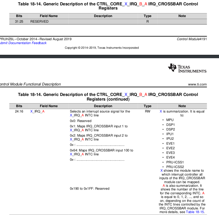 (source pg 4195 of TRM AM57x) The individual connection between all module IRQs and all
 IRQ_CROSSBAR inputs is shown in Section 17.3.12 (Which we have already observed and the image is pasted down below, where we can see corssbar –> MCASP), Mapping of Device Interrupts to IRQ_CROSSBAR Inputs of Chapter 17, Interrupt Controllers.
In addition, the CTRL_CORE_OVS_IRQ_IO_MUX register is used to select for observation on two external pads any IRQ connected to the IRQ_CROSSBAR inputs. Using the CTRL_CORE_OVS_IRQ_IO_MUX[17:9] OVS_IRQ_IO_MUX_2 bit field all IRQs can be mapped to the obs_irq2 signal. The CTRL_CORE_OVS_IRQ_IO_MUX[8:0] OVS_IRQ_IO_MUX_1 bit field maps all IRQs to the obs_irq1 signal. For example, setting the CTRL_CORE_OVS_IRQ_IO_MUX[8:0] OVS_IRQ_IO_MUX_1 to 0x18 maps the GPIO1_IRQ_1 to the obs_irq1 line and thus this IRQ can be observed.
So, infering from what has been said above, we will try to do the following:
- We know, that
CTRL_CORE_OVS_IRQ_IO_MUXis at0x4A00 2D50location. - It has
OVS_IRQ_IO_MUX_1at bits 8:0
and2at bits 17:9 . - McASP rx is
IRQ_CROSSBAR_103which is in hex0x67
and MCASP tx isIRQ_CROSSBAR_104ie.0x68. - for testing purposes, we can use the
devmem2tool to try and set these in the required bits. (note: a word is 16 bits). Once that's done we expect to to have the bit fields mapped toobs_irq1andobs_irq2respectively. - after these bits are set, we can make use of the
CTRL_CORE_X_IRQ_B_Aregisters, specificallyCTRL_CORE_PRUSS1_IRQ_38_39and set the bits 8:0 ie.PRUSS1_IRQ_38and 24:16 ie.PRUSS1_IRQ_39to0x67and0x68respectively. - once this is done, we have a look at
The MII_RT Event Enable Register enables MII_RT mode events to the PRUSS.PRUSS_INTC.
ie. the PRUSS_MII_RT register at address 0x4B22 602C. (Note set the MII_RT_EVENT_EN=0b1) to have PRU-ICSS MII_RT module associated events, mapped to the same lines.
-
In our case, these will be
PRUSS1_IRQ_39and38IRQ input lines. -
Now, referring to
The channel map registers (PRUSS_INTC_CMRi, where i=0 to 15) define the channel for each system interrupt.
and to understand system interrupt, referring to
Enable required system interrupts: System interrupts that are required to get propagated to host are to be enabled individually by writing to INDEX field in the system interrupt enable indexed set register (
PRUSS_INTC_EISR). The interrupt to enable is the index value written. This sets the Enable Register bit of the given index.
which means that we need to write 0x26 and 0x27 to 0x4B22 0028 inorder to enable those two interrupts one by one.
-
It is pobably worth reading the "The next stage is to capture which system interrupts are pending." part, which I am not sure, but think it has been done already in the BELA Pru irq code.
-
Now, we come to
PRUSS_INTC_CMRiregisters located at0x4B22N 0400 + 0X4*i, where i in our case will be channel i=1.
So, we want the system interrupt0x26 and 27to be mapped to channel 1 which when divided by 4 means that we write the value of k as0x9to the bits11:8ie.CH_MAP_1. -
Now that we have mapped the right McASP interrupts to channel 1, which is what the existing BELA PRU IRQ Code checks for already, I think so that the above described workflow should be enough.
PRU-ICSS Interrupt Controller Overview
 The PRU-ICSS interrupt controller (
PRUSS_INTC) maps interrupts coming from different parts of the device (mapped to PRU-ICSS1/PRU-ICSS2 via the device IRQ_CROSSBAR) to a reduced set of PRU-ICSS interrupt channels. The PRUSS_INTC has the following features:
- Capturing up to 64 System Events (inputs).
- Supports up to 10 output interrupt channels.
- Generation of 10 Host Interrupts.
- 2 Host Interrupts for the PRUs
- 8 Host Interrupts exported from the PRU-ICSS for signaling the ARMSS interrupt controllers.
Functional description
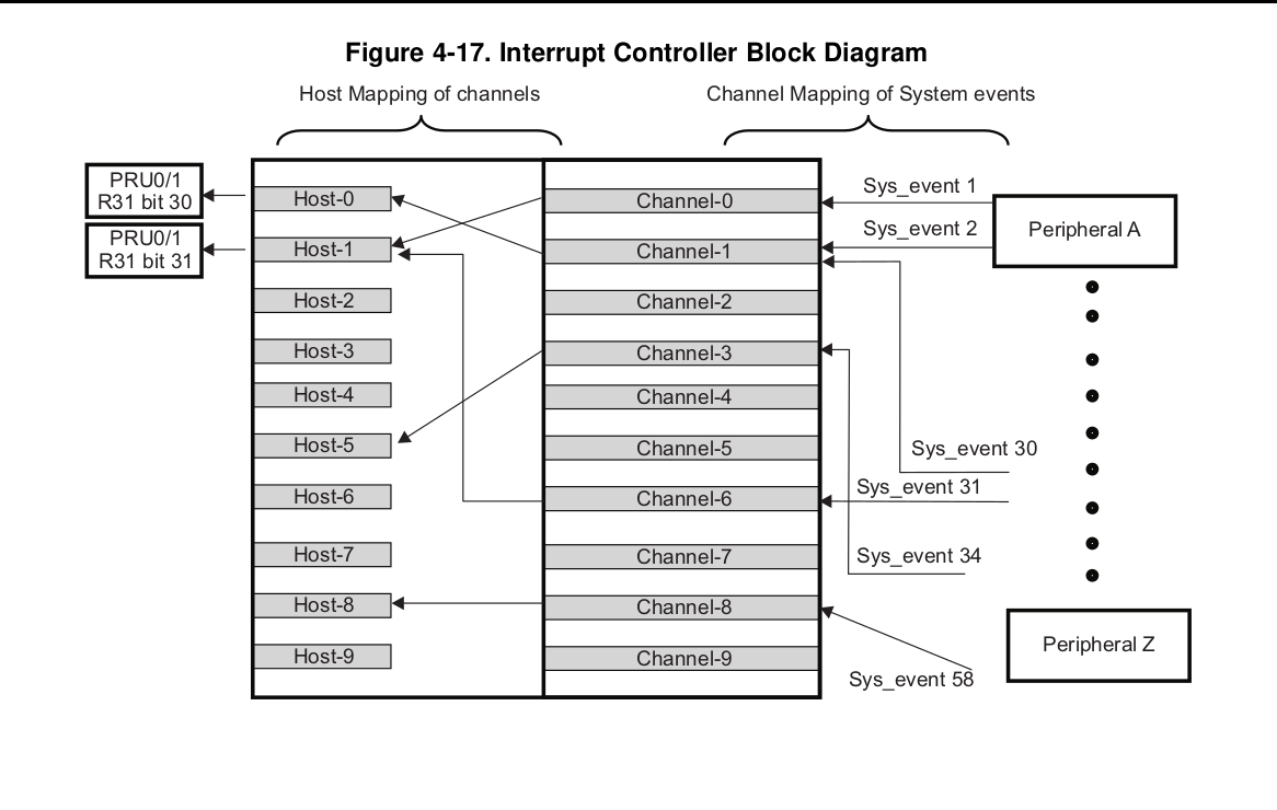
30.1.6.2 PRU-ICSS Interrupt Controller Functional Description The PRU-ICSS incorporates an interrupt controller - PRUSS_INTC that supports up to 64 system interrupts from different peripherals (including 32 interrupts from PRU-ICSS located interrupt sources). The PRUSS_INTC maps these system events to 10 channels inside the PRUSS_INTC (see Figure).
Interrupts from these 10 channels are further mapped to 10 Host Interrupts.
- Any of the 64 system interrupts can be mapped to any of the 10 channels.
- Multiple interrupts can be mapped to a single channel.
- An interrupt should not be mapped to more than one channel.
- Any of the 10 channels can be mapped to any of the 10 host interrupts. It is recommended to map channel "x" to host interrupt "x", where x is from 0 to 9
- A channel should not be mapped to more than one host interrupt
- For channels mapping to the same host interrupt, lower number channels have higher priority.
- For interrupts on same channel, priority is determined by the hardware interrupt number. The lower the interrupt number, the higher the priority.
- Host Interrupt 0 is connected to bit 30 in register 31 (R31) of PRU0 and PRU1.
- Host Interrupt 1 is connected to bit 31 in register 31 (R31) for PRU0 and PRU1.
- Host Interrupts 2 through 9 exported from PRU-ICSS and mapped to interrupt controllers in the device.
30.1.6.2.2.1.1 PRU-ICSS Interrupt Enabling
The next stage of PRUSS_INTC is to enable system interrupts based on programmed settings. The following sequence is to be followed to enable interrupts:
- Enable required system interrupts: The System Interrupt Enable Indexed Set Register allows enabling an interrupt. The interrupt to enable is the index value written. This sets the Enable Register bit of the given index.
Physical Address:
| 0x4B22 0028 | PRUSS1_INTC |
| 0x4B2A 0028 | PRUSS2_INTC |
Table 30-741. PRUSS1_INTC Registers Mapping Summary
| 0x4B22 0284 | PRUSS1_INTC Base addr |
| 0x4B2A 0284 | PRUSS2_INTC |
Table 30-771. PRUSS_INTC_SECR1 talks in detail about the same.
- Enable required host interrupts: By writing 1 to the appropriate bit of the INDEX field in the host interrupt enable indexed set register (
PRUSS_INTC_HIEISR), enable the required host interrupts. The host interrupt to enable is the index value written. This enables the host interrupt output or triggers the output again if that host interrupt is already enabled. ref. Table 30-231. PRUSS_INTC_HIEISR
Physical Address:
| 0x4B22 0034 | PRUSS1_INTC |
| 0x4B2A 0034 | PRUSS2_INTC |
- Enable all host interrupts: By setting the ENABLE bit in the global enable register (
PRUSS_INTC_GER) to 1, all host interrupts will be enabled. Individual host interrupts are still enabled or disabled from their individual enables and are not overridden by the global enable. (we probably do not need this)
Note: Checkout 30.2.6.2.2.2 PRU-ICSS Interrupt Status Checking of AM57xx Manual, just to be sure that the BELA PRU code is using the right register locations to check the interrupt statuses.
30.2.6.3 PRU-ICSS Interrupt Controller Basic Programming Model
Follow these steps to configure the interrupt controller.
-
Set polarity and type of system event through the System Interrupt Polarity Registers (
PRUSS_INTC_SIPR1andPRUSS_INTC_SIPR0) and the System Interrupt Type Registers (PRUSS_INTC_SITR1andPRUSS_INTC_SITR0). Polarity of all system interrupts is always high. Type of all system interrupts is always pulse. - Map system event to
PRUSS_INTCchannel throughPRUSS_INTC_CMRi(i=0 to 15) channel mapping registers. - Map channel to host interrupt through
PRUSS_INTC_HMR0/1/2registers. Recommended channel "x" to be mapped to host interrupt "x". - Clear system interrupt by writing 1 to
PRUSS_INTC_SECR0/1registers. - Enable host interrupt by writing index value to
PRUSS_INTC_HIEISRregister. - Enable interrupt nesting if desired.
- Globally enable all interrupts through register
PRUSS_INTC_GER[0] ENABLE_HINT_ANYbit.
Routing McASP0 interrupts to PRU INTC
Let's take PRUSS_INTC_CMR0 and 1. As per Table 30-781 PRUSS_INTC_CMRi the physical addresses will be:
0x4B22 0400 + 0 –> for ...CMR_0
0x4B2A 0400 + 4 = 0x4B2A0404 –> ...CMR_1
and then we have to set the bits according to this table: 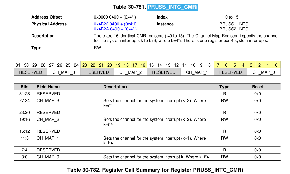 Here, we will set the bits 3:0 ie.
 CH_MAP_0
pg 6076:
MCASPi_IRQ_AREVTcan be also generated if theRDATAinterrupt is enabled in theMCASP_EVTCTLRregister (for details, see Section 24.6.4.12.1, Receive Data Ready Interrupt).
From table 17-11. PRUSS1_INTC Default Interrupt Mapping (continued) Let's use the PRUSS1_IRQ_38 which is Reserved by default but can be remapped to a valid interrupt source and also PRUSS1_IRQ_39. From pg 43821 Table 18-553,
Addr offset: 0x0000 08D4 Physical Address: 0x4A00 28D4 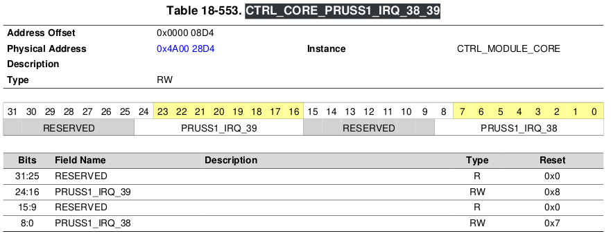
PRUSSDRV to RPROC
-
The basic unit of communication between remoteproc and the PRU as of now is using downcalls and syscalls.
-
A syscall is when the PRU raises an IRQ and halts itself, storing some values in its registers. The kernel module handles the syscall IRQ, it reads the registers, manipulates them and resumes the PRU over the HALT instruction. See here for an example code of the syscall on the PRU side.
-
A downcall is initiated by the kernel module. Think of it as calling a function in the PRU from the kernel module and receiving the return value back in the kernel module.
Note: The PRU has to be polling for the downcall, and it acknowledges with a special syscall. Then the functionhandle_downcallis called, which receives the downcall value and the parameters. So thehandle_downcallexample is a switch-case thing where the PRU does something and once it returns from this function, there is a syscall triggered which signals that the downcall is complete, the kernel module reads the return value of the function, after which the downcalling function in the kernel module returns with the return value. -
the crux is that remoteproc currently is very application-specific and you have to twist and adapt the kernel module to your needs. Once the remoteproc stuff gets finalized, ideally there would be a generic framework and userspace layer on top of the driver to allow you to write your own applications from userspace, in a similar way as it is currently done using libprussdrv.
Common Terms used
- PRU-ICSS: Programmable Real-Time Unit Subsystem and Industrial Communication Subsystem.
- Arm interrupts: Refer this tutorial
References
- TI Forum: am3359-routing-mcasp0-interrupts-to-pru-intc
- TI-forum: gpio crossbar settings
- mail-archive: Using irq-crossbar.c
- TI Forum: am572x-interrupt-mapping-for-dsp-and-gmac
- TI:hwi-event-mapping
- BB-archive:prussdrv-to-remoteproc
Misc.

pg4163
CTRL_CORE_PRUSS1_IRQ_32_33 RW 32 0x0000 08C8 0x4A00 28C8